Over-wide notch or strong IIR notch
Symptom. Gamma hole and ringing around 50/60 Hz.
1 claim on this page is unverified. TODO(confirm) marks a specific statement the author has not yet checked against a
primary source. Everything else on this page has been reviewed. Treat a marked claim as
provisional and go to the cited source rather than quoting the sentence.
Symptom
A spectral hole several Hz wide around the mains frequency that removes physiological activity along with the line; a “dip” in gamma power at 45–55 Hz (50 Hz mains) or 55–65 Hz (60 Hz mains) that is the notch, not the brain; and ringing — a decaying oscillation at the notch frequency — around every transient (electrode pops, stimulus artifacts, blinks) after filtering. In time-frequency maps the ringing appears as a horizontal band at the mains frequency following each transient.
Cause
A notch is a band-stop filter. Making it wide (to be sure of catching a line that drifts, or several harmonics at once) removes the whole band; making it sharp and deep with a high-order IIR gives it a long, oscillatory impulse response at the notch frequency, so any sharp feature in the data is followed (and, with zero-phase filtering, preceded) by a ringing tail. The two errors are usually made together: a default notch is often both wider and deeper than the line noise requires.
Detect
- Inspect the filter’s impulse response: a notch that rings for hundreds of milliseconds will ring in the data.
- Compare PSDs before and after: a well-designed notch removes a line and leaves the neighbouring power unchanged; a hole wider than about 1–2 Hz (TODO(confirm) a sensible width) is removing more than the line.
- Filter a segment containing an electrode pop and look for oscillation at the mains frequency on either side of it.
- Compute residual power in a narrow window around the mains frequency relative to the flanks before and after; the goal is a flat spectrum, not a hole.
Fix
- Use the narrowest notch that removes the line; MNE’s
notch_filterFIR default, or its spectral-fit method (method='spectrum_fit'), removes the sinusoid rather than the band. - Consider spatial methods that subtract the line-noise subspace without touching the spectrum elsewhere (ZapLine, L1.6).
- Notch each harmonic that lies below the Nyquist frequency separately, with the same care; do not widen the notch to catch a drifting line — remove the drift’s cause or use spectral fitting.
- Verify: PSD before and after, a transient before and after, and a residual-power metric, all reported.
- If a hardware notch was already applied (as in
ds-arithmetic), do not notch again — see pf-notch-hole-in-band.
Example
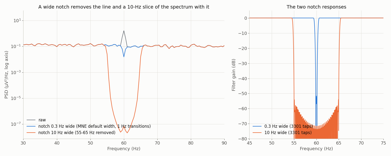
ds-iowapd sub-001, Oz, 60 s from 160 s, 500 Hz. MNE notch_filter at 60 Hz with the default 0.3 Hz width removes the mains line and little else; a 10 Hz wide notch carves a hole across 55-65 Hz that would read as ‘less gamma’ downstream. Welch PSD, 2-s Hann segments; zero-phase FIR notches (firwin, Hamming). Generated by data/scripts/make_figures.py from ds-iowapd (CC0).